Architectural Building Blocks: 5 AutoCAD Tips and Tricks
ArchiHacks is an online resource for architects dedicated to architecture visualization, portfolio, and design tips and tricks for students and professionals. This article was written by team member Tommy Minh Nguyen.
Not everyone may have the chance to use AutoCAD, but sooner or later, you will probably end up using some form of computer-aided drafting (CAD), which will have a similar workflow. AutoCAD was developed and marketed by Autodesk for architects, engineers, and construction professionals to create precise 2D and 3D drawings. The strides in architecture technologies in recent years catapulted the design and construction of amazing projects. For many emerging professionals, AutoCAD isn’t on the radar anymore (even if they are entering the workforce with extensive knowledge of new software). Yet, even if everyone talks about Revit, Grasshopper, Rhino, and all the sorts of BIM or 3D modeling software, AutoCAD is still utilized in firms all across the world.
If you aren’t familiar with or used AutoCAD much, it’s okay — we will be sharing five tips that will facilitate a quicker workflow of the industry’s staple that is still around! Besides, being familiar with AutoCAD can establish a good foundation for other programs. It’s important to note that the images below are stitched to illustrate the process better, so it will not look the same when attempting this.
Shortcuts + Customization
One of the greatest hacks for any software is learning the shortcuts. This may not be news, but what if I said you could customize the shortcuts in AutoCAD even further? I recently learned this trick and thought, ‘Had I known this sooner, I would have saved so much time.’
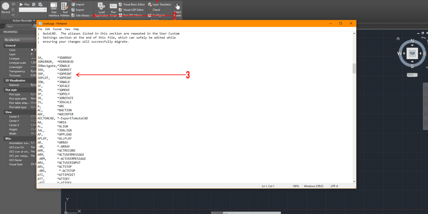
How do you set up your own shortcuts? When you open up AutoCAD, you’ll want to click on the “Manage” tab, then click on “Edit Aliases,” and this window should pop up.
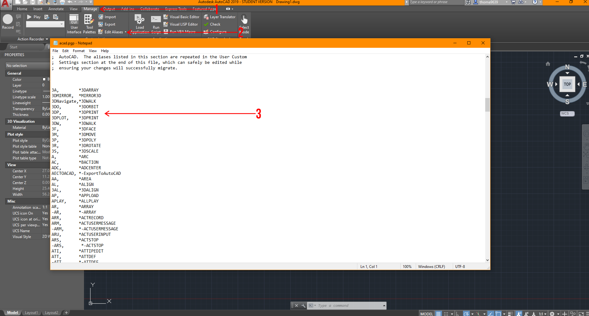 From here, you can customize all the shortcuts you need to one or a few keys to do multiple tasks. It’s important to make sure there are no duplicates in this notepad, or AutoCAD will be confused about what you are attempting to achieve.
Interface Customization
Just like shortcut customization, interface customization is the next best thing to get situated with. When I’m opening a new software, the first thing I always ask is “How do I switch this to black or dark scheme?” Luckily, it’s effortless. Type “Settings” in the command bar, and a window will pop up, which will give you multiple options to adjust the display, drafting, or user preferences settings. Take the time to explore those options and adjust to your liking! In addition, there are other ways to customize your interface, and I’ll break down some things in the image below,
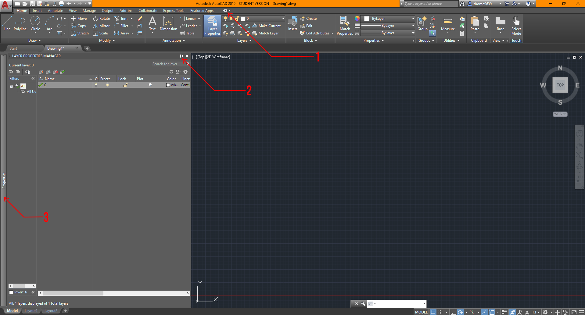
- This button controls the ribbon area, and you can cycle through multiple settings depending on how you like it. I normally go with the ribbon option shown in the image because it’s easier to navigate than the others.
- This option is available for most pop-up tabs that occur in AutoCAD. This symbol essentially asks if you’d like this window to be added to your sidebar. It also toggles whether you want the tool window to stay locked or hidden when not used.
- The sidebar is where you’d find any anchored tool window you’d like. I usually keep my properties tab locked but place my “Layer Properties” and “External References” anchored and automatically withdrawn if not used to the side for quick access.
Utilizing Blocks
Looking back, I realized how much time I wasted without using blocks. Instead of repeatedly deleting and copying objects, I could have made changes to one block and it will change all of them in AutoCAD! Blocks essentially allow you to edit multiple instances of the same block at once.
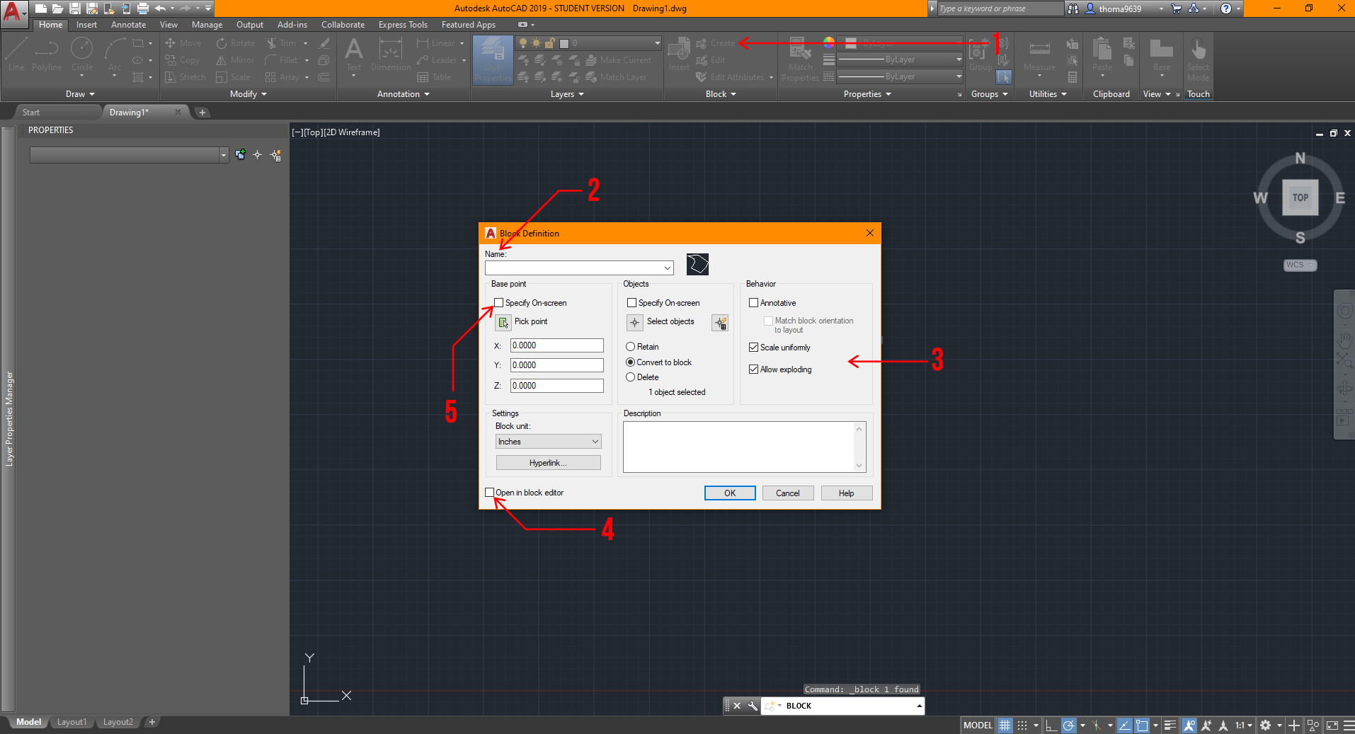
There are two effortless ways to access it: option 1 is found under the “Home” ribbon, where you can go over to the block tab to create or insert any blocks. Option 2 is housed under the “Insert” ribbon — there’s a bigger block tab that can help you learn what the image stands for, but either option will get you to the same result. Ideally, you’d want to create the object first using any tools under the option and modify tab. Once you’ve done that, select the lines, then click the “Create Block” button and this window should pop up.
 You can choose to select the object after, but I find it easier and quicker to select the lines or objects first before creating the block.
- Click this button for the “Block Definition” window to pop up after selecting the lines and/or objects for the block.
- This is where you should name the block so it will save you time finding it!
- These are some settings you’d want to adjust eventually; for your sake, the settings shown will be ideal before adjustments.
- It’s ideal to uncheck this box because it’s unnecessary to edit the block right away if you’ve drawn it correctly beforehand. Don’t worry, you can always edit the block by right-clicking the object and finding the “Edit Block” option.
- Make sure to select this option to set the base point of the block. Otherwise, it may cause complications later on!
Utilizing xRefs or xReferences
Another great hack in AutoCAD is learning how to operate xRefs; they are essentially any viable file that can be placed into the drawing to use as a reference, like PDFs, JPGs, or other AutoCAD files (DWGs). This could be extremely helpful if you were making an addition to other projects, or your project has specific site conditions you’d want to display.
This is also great practice in professional settings for several reasons. First, it allows multiple people to work on different files and still reference each others’ work. Second, it keeps each file clutter-free, lightweight, and focused on the relevant parts of the project. Third, it allows you to swap out versions or iterations by replacing xRefs quickly. Here’s how you can bring one in:
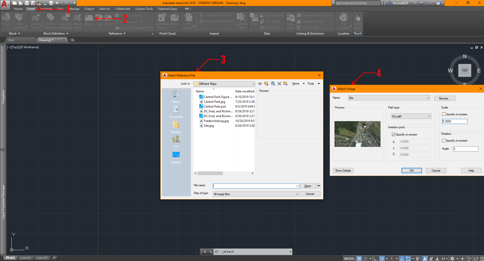
- Click on the “Insert” ribbon.
- After that, go ahead and click on “Attach.”
- This window will pop up for you to select what file you want to use as a reference.
- After making your selection, a second window will pop up, and I have already set general settings for your convenience. You could make more adjustments to these settings once you have learned the process!
Sheet Layout + Viewport Control
Let’s say you want to export a drawing without certain features but don’t want to waste time to recreate it or copy multiple views causing your file to slow down. What do you do? Sheets and viewport control are your best friend! Now, I never really used this feature until I began working, but still, I’m sure it will save you some time too! Assuming that you have a drawing in AutoCAD and it’s situated near the origin (0,0) in the model space, here are the steps you can do to maximize your efficiency in exporting views.
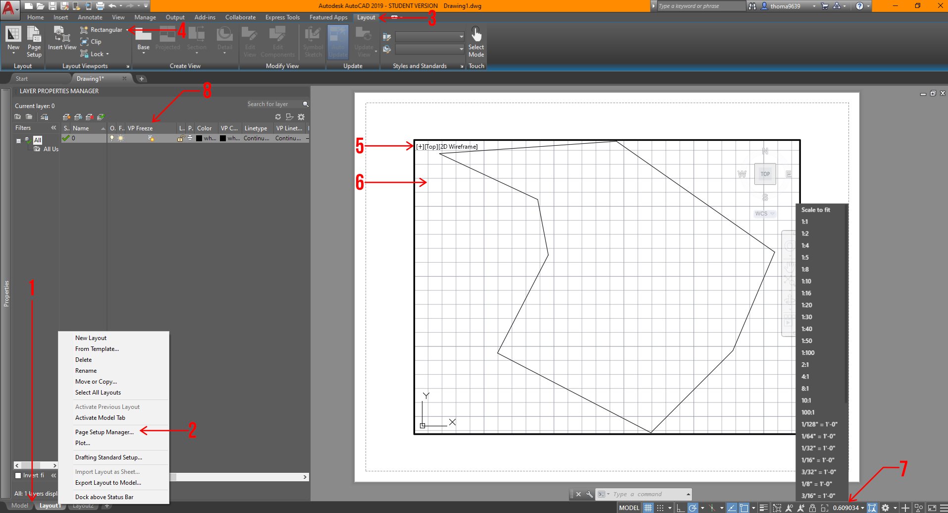
- In AutoCAD, the space you work in is called the “Model” space, so if you want to control your sheets for drawings and views, you will want to click on the tabs below to set that up. You can add sheets by hitting the “+” sign or right-click on a tab to add a sheet.
- You should confirm the sheet size or settings you will want to export the drawing in by right-clicking the sheet tabs and clicking the “Page Setup Manager” option. From there, another window will open and a few more adjustments based on your needs.
- Select this tab to create a viewport or view on the sheet. Viewports is another way to see your drawing, imagine it’s a camera snapshot of the model space, which you can control certain settings that won’t affect the model space!
- To create a viewport, click on this item. Now, you can have organic-shaped viewports, but in this scenario, let’s keep it simple. Once you click on it, all you have to do is draw a rectangle that fits your sheet, and you can always adjust if needed.
- This is the rectangular viewport.
- You can double-click into the viewport and use the mouse wheel to locate what you want visible in the box. If you want to exit the viewport space, double-click on the sheet or the colored edge surrounding the drawing.
- After selecting the frame of the viewport, you can control the scale of the drawing by clicking on the scale symbol at the bottom right corner. Make sure to lock the view by clicking the lock symbol next to the scale symbol. This makes your viewport fixed on what you are showing.
- You can turn off layers in specific viewports by opening your “Layer Properties,” finding the tab that says “VP Freeze,” and clicking on the symbol with the sun. This is similar to freezing a layer, but instead of turning it off for the entire file, it will only turn it off for that view.
This is a rather advanced technique in AutoCAD, so there’s a lot of playing around with this last one. However, if you learn this sooner, especially with the iterative process of school and work, it can save you a lot of time and headaches.
These tips vary in levels of understanding of AutoCAD; nonetheless, these should help you learn the software even faster. That’s all we got for today! I hope you found this article helpful, and if you have any tips for future students, please let us know in the comments below. Make sure to follow Archi Hacks’ YouTube and Instagram for more content.
Send Us a Rendering. Tell Us a Story. Win $2,500! Architizer’s 3rd Annual One Rendering Challenge is open for entries, with a Regular Entry Deadline of March 11th, 2022. Submit a rendering.


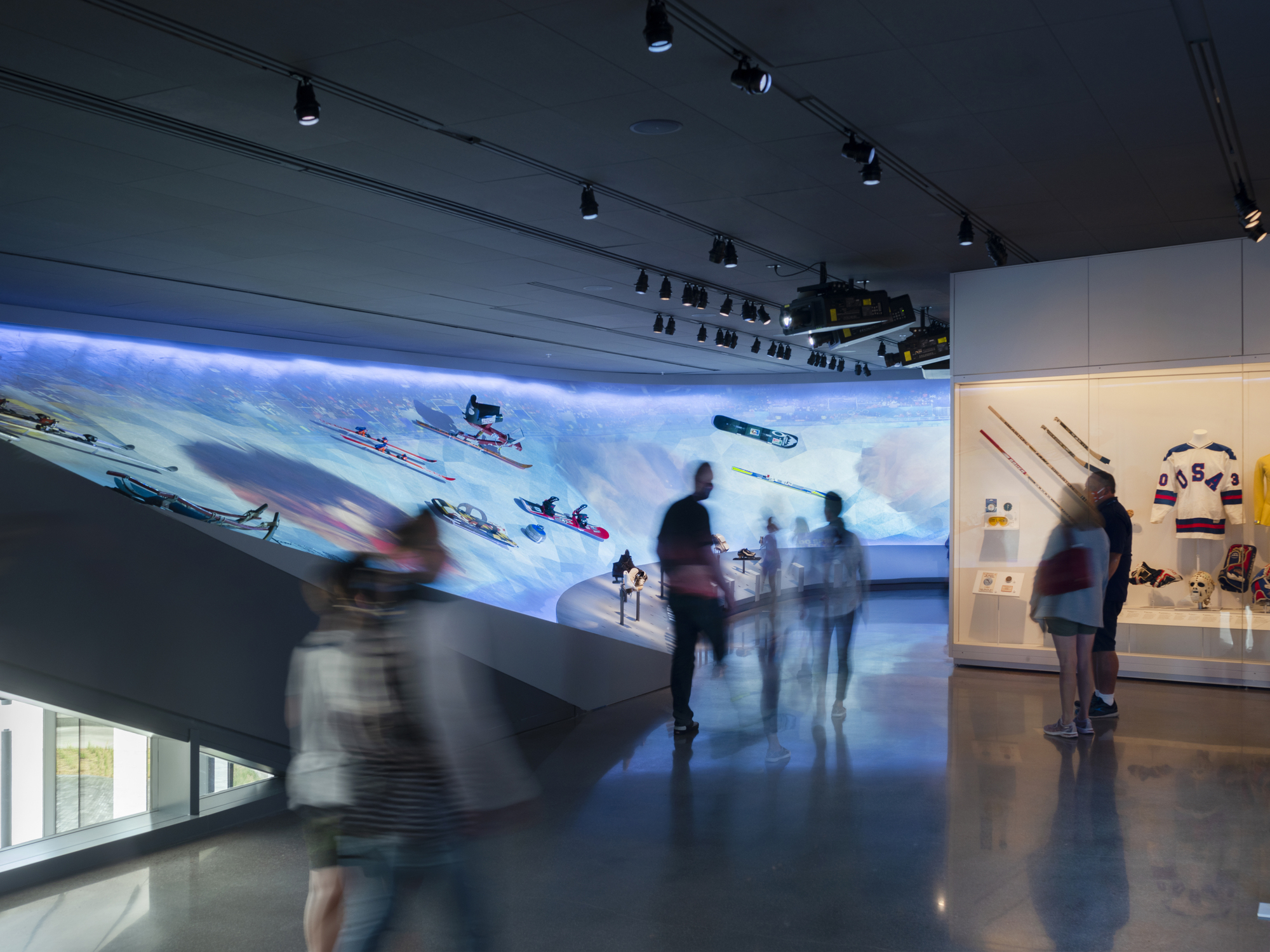
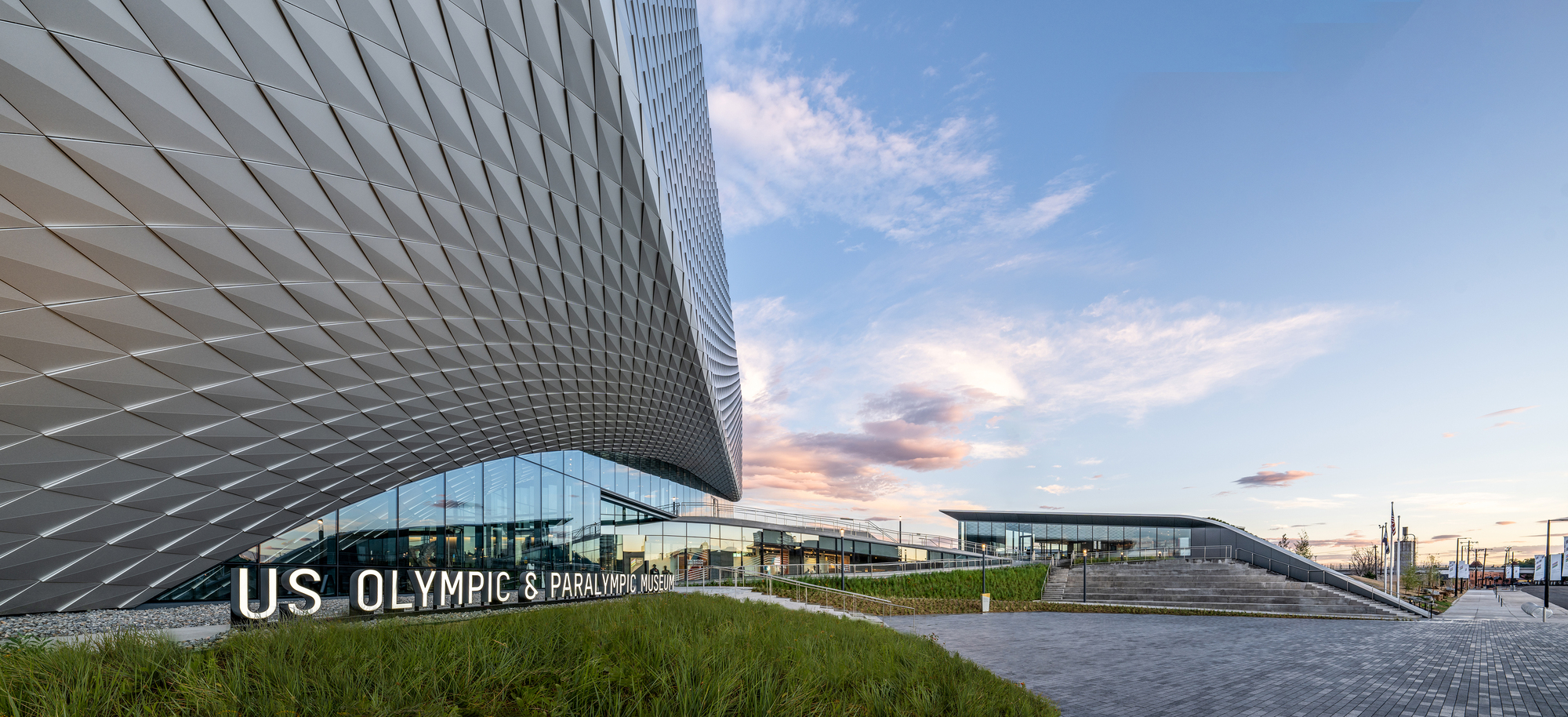 Ten years in the making, the United States Olympic and Paralympic Museum (USOPM) opened in 2020 as the first building of its kind to pay tribute to Olympic and Paralympic movements. The 60,000 square foot design features galleries, a state-of-the-art theater, event space and café, and was inspired by the energy and grace of Team USA athletes and the organization’s inclusive values.
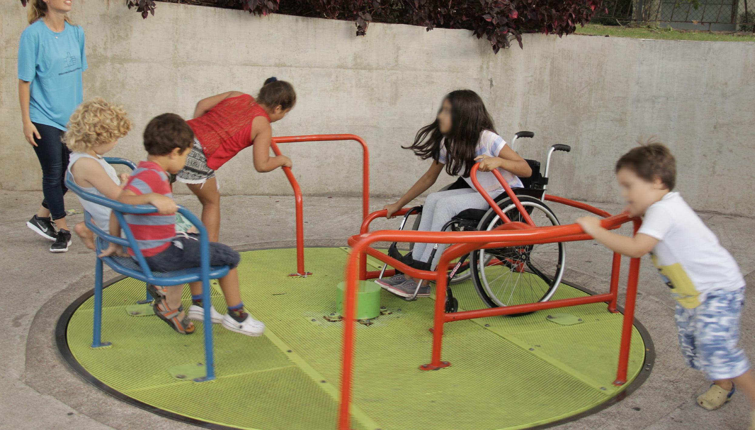
 From the earliest stages of design, the team consulted Team USA athletes, including Paralympic athletes and persons with disabilities, to ensure the most authentic and inclusive experience. Ramps guide visitors down a gentle-grade downhill circulation path that enables easier movement. These ramps have been widened to 6 feet to accommodate the side-by-side movement of two visitors including a wheelchair.
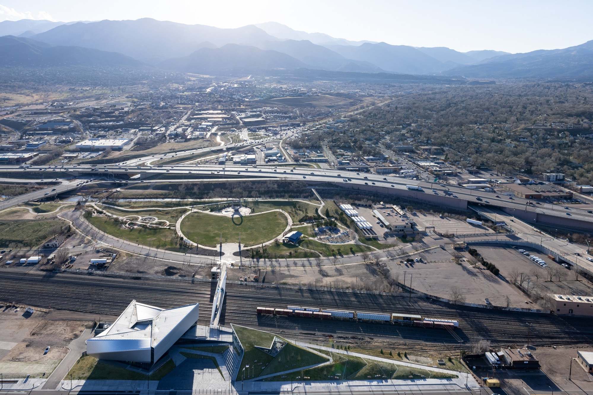
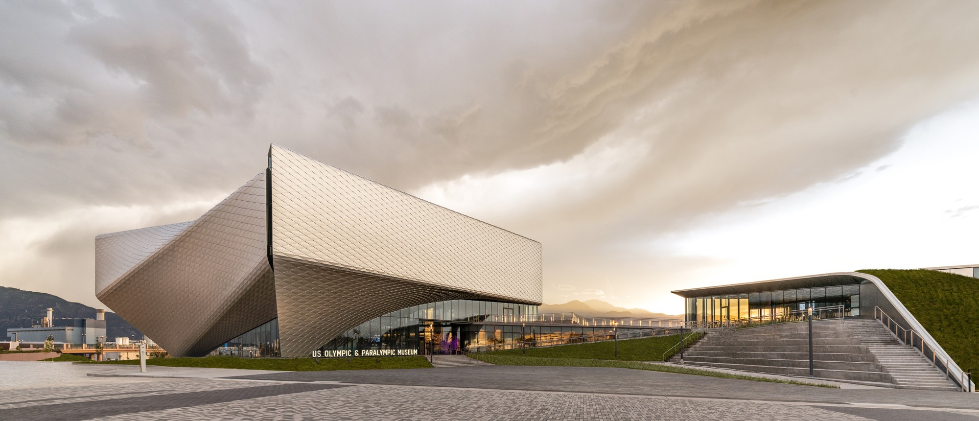 Outside, a terraced hardscape plaza is at the heart of the museum complex, with the museum building to the south and the café to the north. In addition, the Park Union Bridge is a 250-foot curved steel structure that floats above an active railyard. Two interlocked loops, stretching from either side of the railyard, connect the museum and America the Beautiful Park.
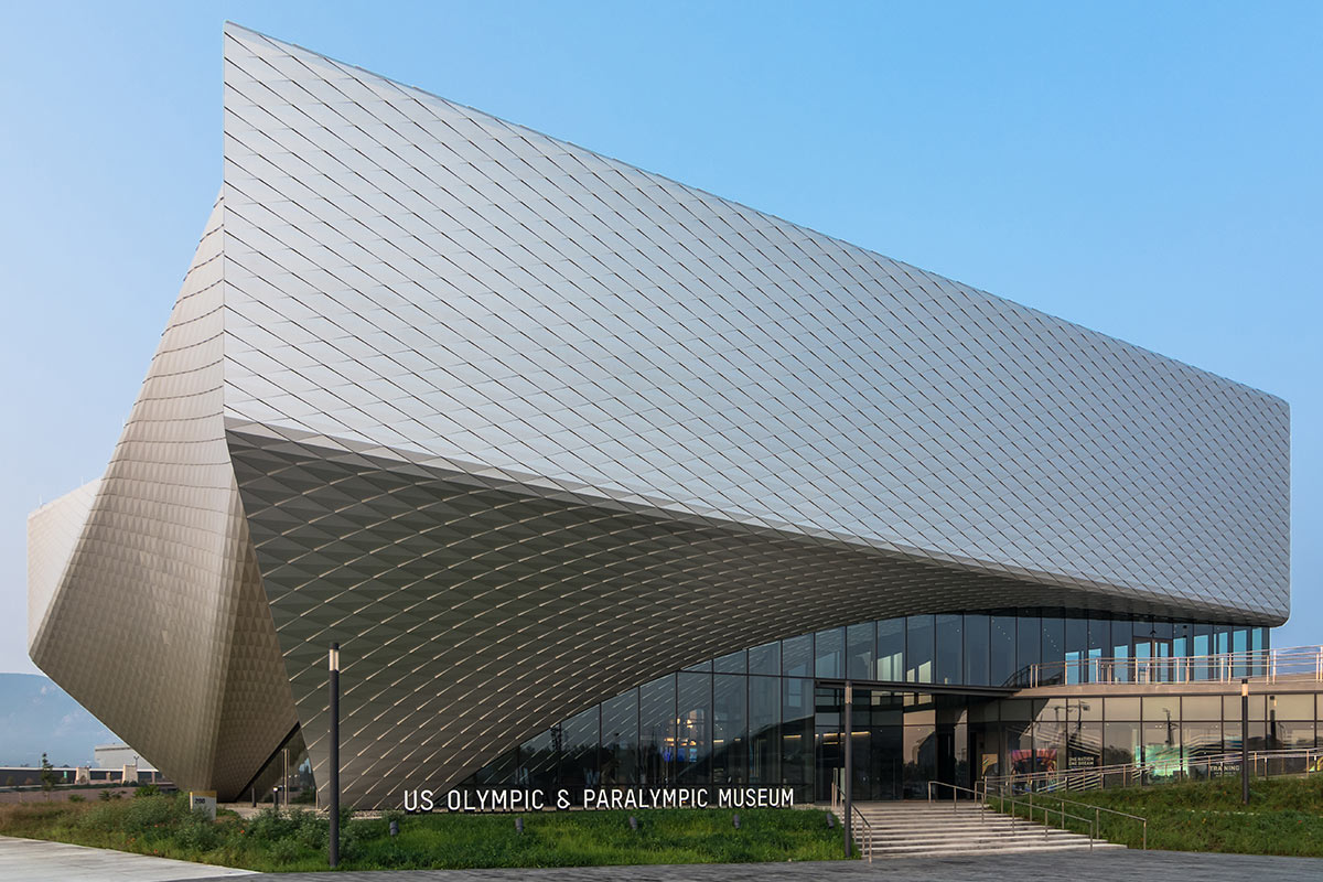
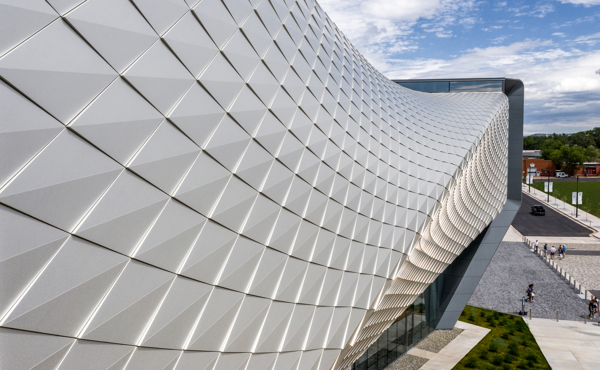 Diller Scofidio + Renfro worked with Lorin Industries on the aluminum panels, as well as MG McGrath and Oldcastle BuildingEnvelope on the curtain walls. Bringing the vision of the building’s exterior to life, the teams wanted to create a building structure and overall exterior visual effect that encapsulated the passion, dedication, and endurance of an Olympic athlete. To achieve this, a system of custom metal panels with integrated gutters wrap the double-curved geometry of the façade.
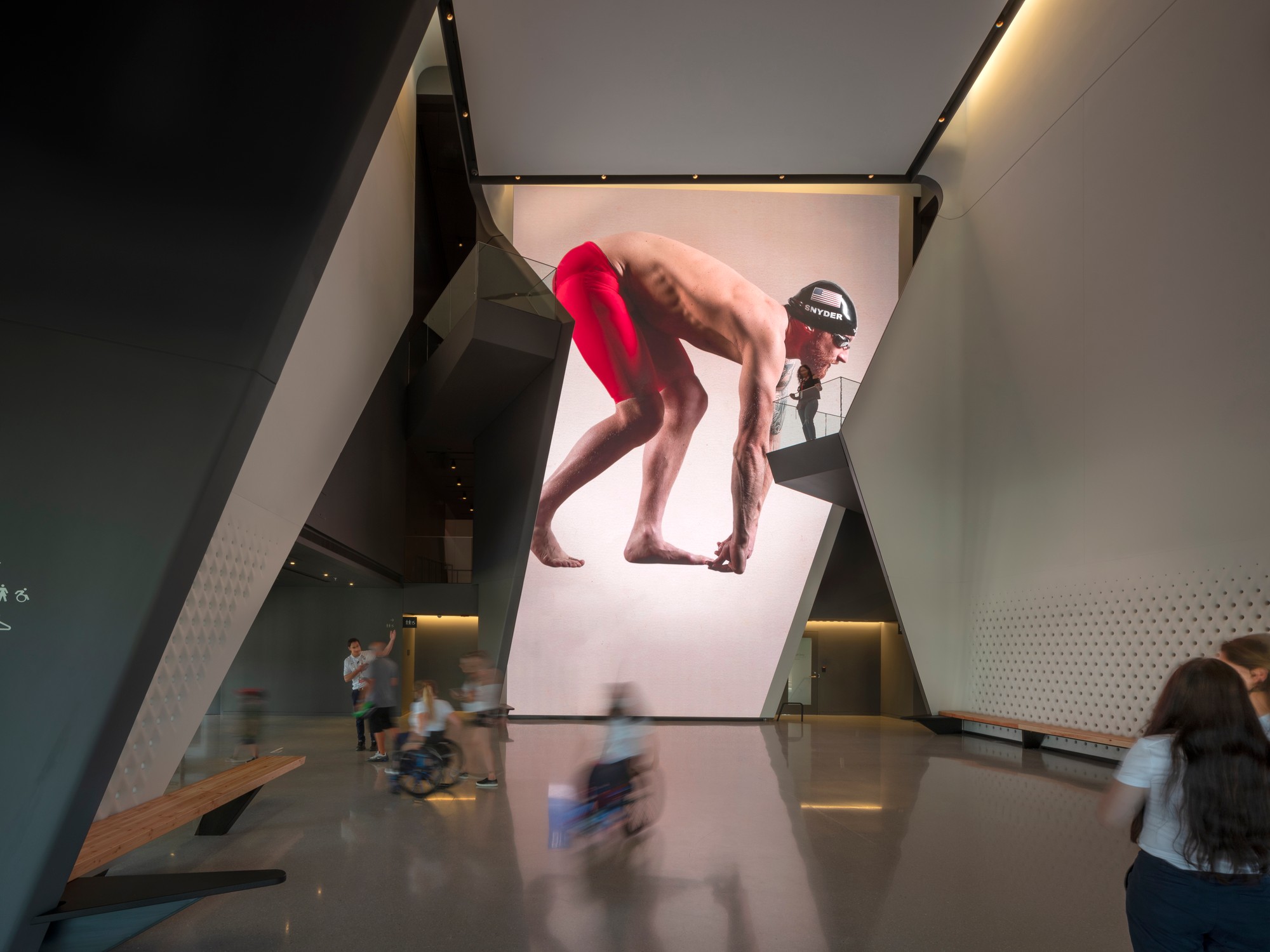
 Lorin pioneered the coil anodizing process, which protects the aluminum while also improving its aesthetic properties and durability. The panels are 100% recyclable helping to meet the project’s LEED requirements. Lorin’s anodized stainless finish is created by an electro-chemical process that builds an anodic layer from the aluminum, molecularly bonding it to the surface. It protects aluminum from oxidation, scratching, and other hazards far better than natural oxidizing, and it requires minimal upkeep while resisting scratches and finger prints. Even with its light weight, coil anodized aluminum has an exterior surface hardness second only to diamond and is therefore unmatched in abrasion resistance and durability.
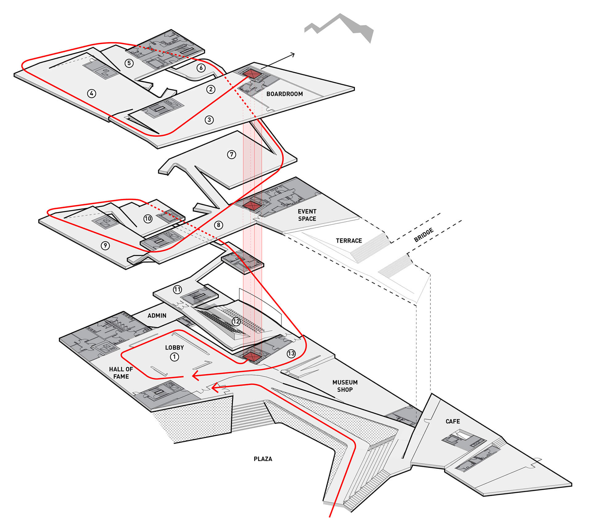
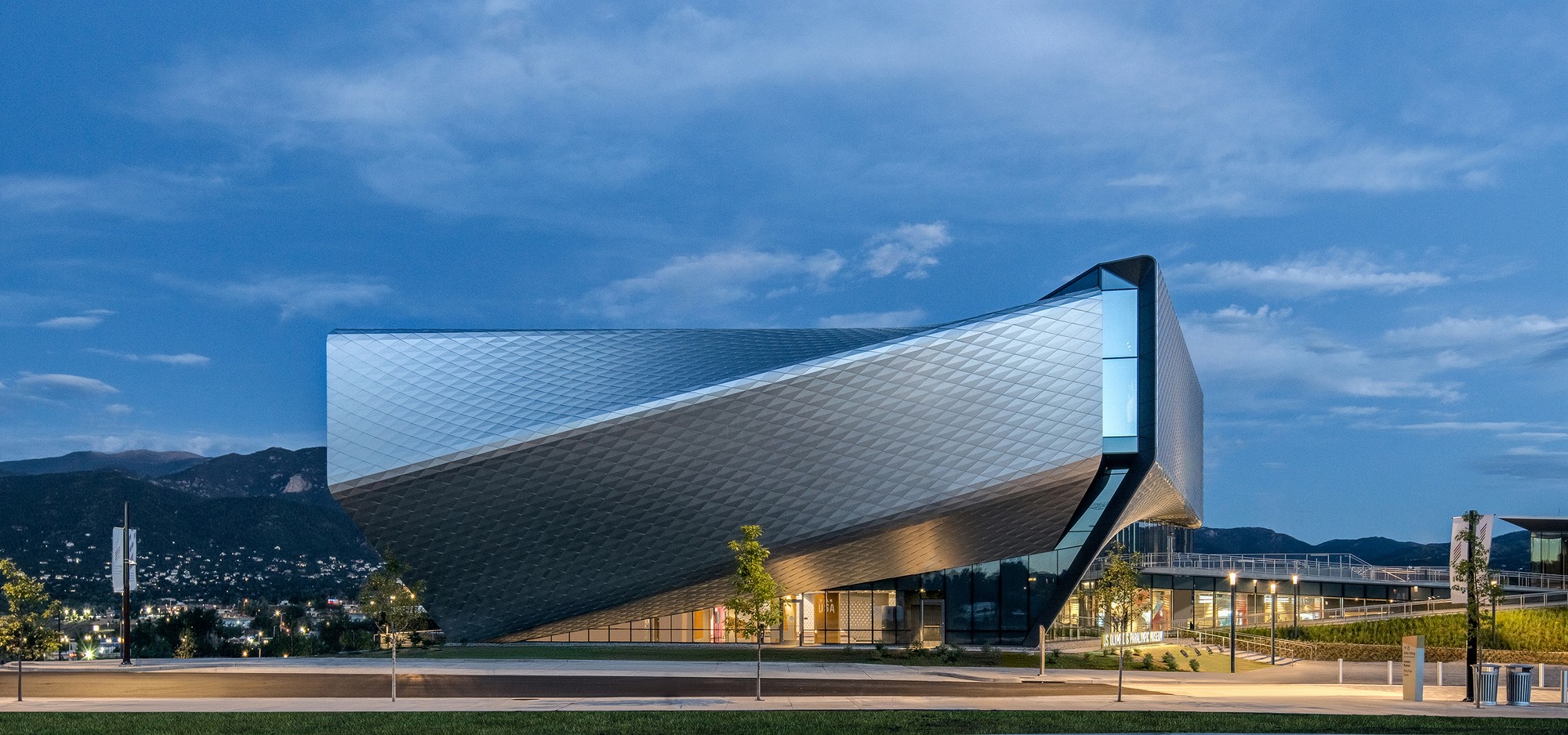 Putting Team USA athletes at the center of the museum experience, the design team created a museum that’s as functional and accessible as it is beautiful. The design rises with the primary structural systems consisting of a steel frame superstructure, drilled shaft caisson foundations, and cast-in-place concrete lateral cores. From this, the exterior shell further accentuates the dynamism of the building concept and purpose, with each metallic panel animated by the extraordinary light quality in Colorado Springs, producing gradients of color and shade that give the building another sense of motion. If great architecture reflects a common purpose and creates rich experiences, this is certainly the case in DS+R’s United States Olympic and Paralympic Museum.